How to Draw Lines in WebGL
Recently, I wanted to create some interactive canvas effects. To make the visuals as dynamic as possible while taking advantage of GPU acceleration, WebGL and Three.js were natural choices. Writing code with Three.js is quite a pleasant experience, but I soon ran into a major roadblock: it’s surprisingly hard to freely draw a line in Three.js.
lineWidth Does Not Work
In Three.js, you can draw lines using LineBasicMaterial. By passing point coordinates into BufferGeometry, you can achieve the desired effect:
const points = [p1, p2, p3];
const material = new THREE.LineBasicMaterial( { color: 0x0000ff } );
const geometry = new THREE.BufferGeometry().setFromPoints( points );
const line = new THREE.Line(geometry, material);
Sounds pretty straightforward, right? However, once rendered on screen, you’ll notice the line is far thinner than expected—in fact, it’s strictly 1px. I initially assumed it was a bug, but upon checking the documentation, I found:
Due to limitations of the OpenGL Core Profile with the WebGL renderer on most platforms linewidth will always be 1 regardless of the set value.
In other words, even though OpenGL provides a lineWidth API, most platforms (almost all major browsers) ignore this call and default to 1.
To verify my understanding, here is an example written in pure WebGL:
See the Pen webGL-line by 愷開 (@kjj6198) on CodePen.
function main() {
  var gl = initGL();
  var shaderProgram = initShaders(gl);
  var vertices = createPoints(gl, shaderProgram);
  gl.lineWidth(100.0);
  draw(gl, vertices);
}
As you can see, even after calling gl.lineWidth(100.0), the rendered line width is still just 1. Nowadays, screens are 4K or higher, and a 1px line looks terribly thin and jagged. Clearly, relying on gl.LINE_STRIP or gl.LINE won’t work (unless that’s specifically the aesthetic you’re after).
Checking MDN’s documentation confirms this limitation:
The maximum minimum width is allowed to be 1.0. The minimum maximum width is also allowed to be 1.0. Because of these implementation defined limits it is not recommended to use line widths other than 1.0 since there is no guarantee any user’s browser will display any other width.
Ironically, the only platform that actually implemented lineWidth was IE11—how’s that for a twist?
Using Other Geometries
Since Line doesn’t cut it, could we brute-force it with PlaneGeometry or ShapeGeometry?
Technically yes, but built-in geometries have predefined vertices, making dynamic adjustments cumbersome. Moreover, if we’re just drawing lines, I’d prefer keeping the vertex count to an absolute minimum.
Searching through the Three.js documentation, there didn’t seem to be any built-in Line variant with customizable line width. I was quite surprised by this lack of support—doesn’t everyone need to draw lines at some point?
Other Libraries
Although there is no built-in primitive, Three.js does provide a fat-line example that supports custom widths and even dashed lines. I initially considered adopting it directly, but integrating it into my current setup felt a bit overkill.
Another option is THREE.MeshLine. It looks feature-complete and straightforward to implement. However, its coding style is somewhat dated, and it offers far more features than what I actually need.
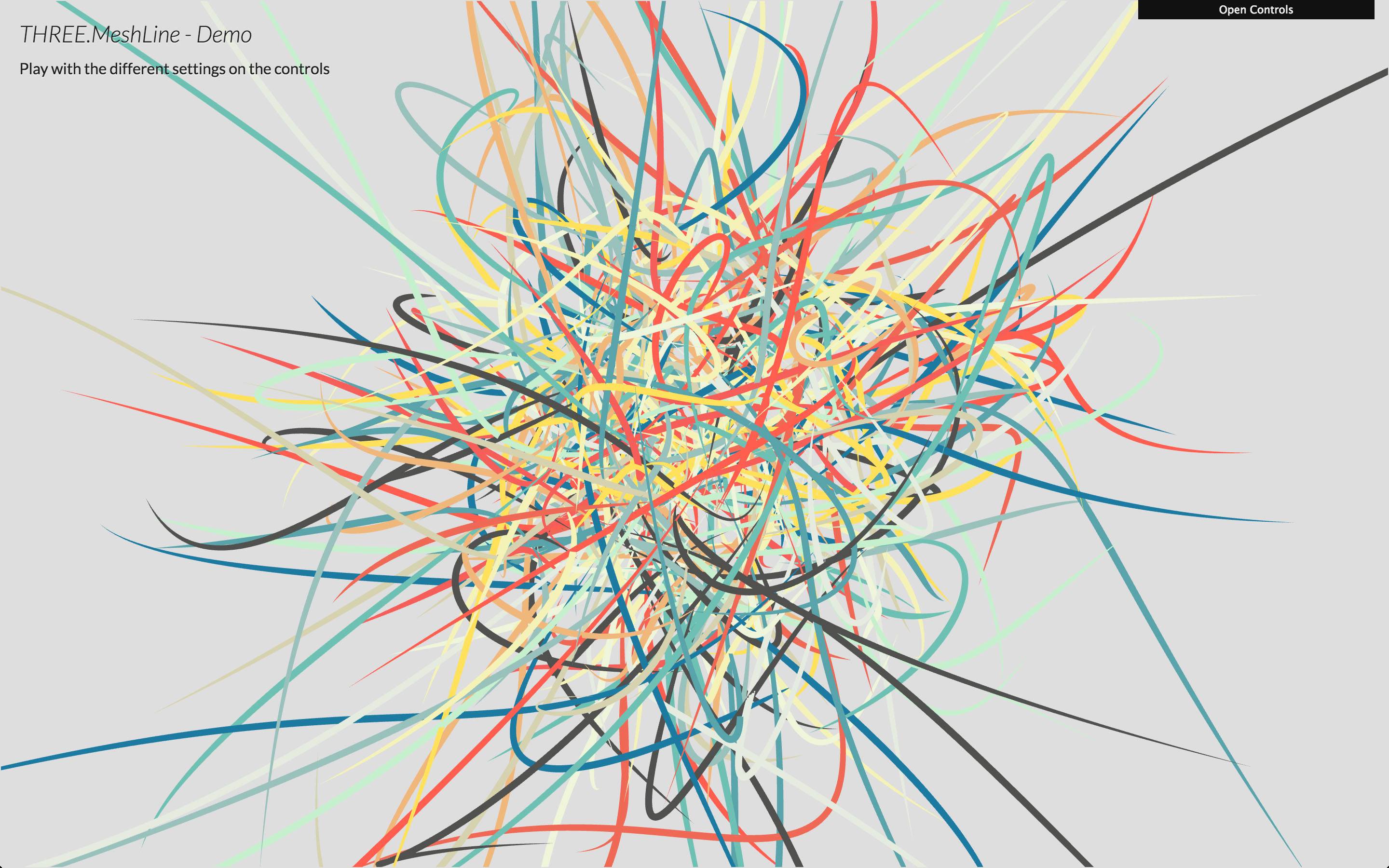
Summing up my requirements, all I need is:
- Feed in points and draw a line
- Adjustable width
- Adjustable color
So, I decided to build one myself.
Solution: Forming Surfaces from Points
Given three points, drawing a line connecting them is straightforward—you simply join the points in sequence. In fact, that’s exactly how gl.LINE_STRIP or gl.LINE works. But as mentioned earlier, lineWidth is locked to 1. To expand the line’s thickness, we must construct surfaces using gl.TRIANGLE instead.
For the vector formed by every two points, we can compute its normal vector and offset two points perpendicularly (above and below):
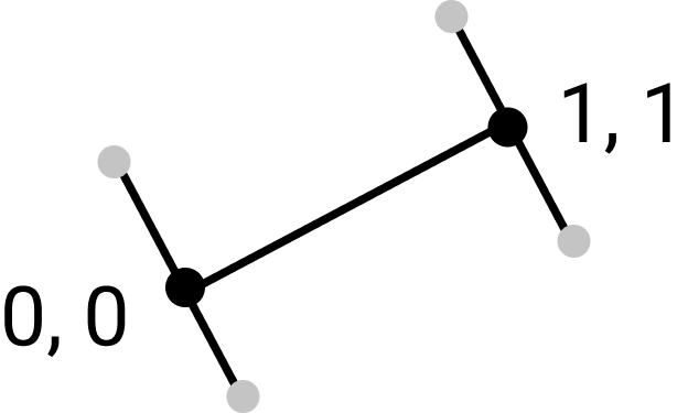
Here, the gray dots represent the target vertex positions, which are then passed as vertices to the vertex shader.
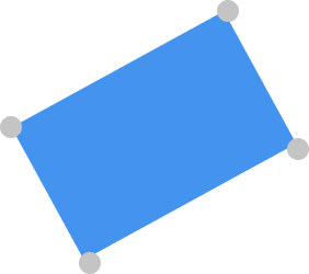
This keeps the vertex count to a minimum while giving us full control over line width.
Implementation
Given two points and , they can be represented by a linear equation: . What we need to do is find a vector perpendicular to this line passing through P1 and P2—that is, the normal vector.
Let’s start with P1: we find the vector , whose normal vector is . We can then offset one point along the positive and negative directions of the normal, at a distance of lineWidth / 2. We do the same for P2, offsetting one point in each direction. This gives us four points in total, forming a quad (two triangles).
As an aside, a triangle is drawn only after the vertex shader is invoked three times, meaning two triangles normally require 6 vertex coordinates. To avoid wasting memory on duplicate vertices, we use an index array to instruct WebGL how to access the vertex coordinates.
const indices = [0, 1, 2, 2, 1, 3]; // Tells WebGL the order to access vertices
const indexBuffer = gl.createBuffer();
gl.bindBuffer(gl.ELEMENT_ARRAY_BUFFER, indexBuffer);
gl.bufferData(gl.ELEMENT_ARRAY_BUFFER, new Uint8Array(indices), gl.STATIC_DRAW);
Method 1: Computing the Normal for Each Point
For every two points, find the vector, determine its normal vector, and offset upward and downward by the segment length. Here is the result:
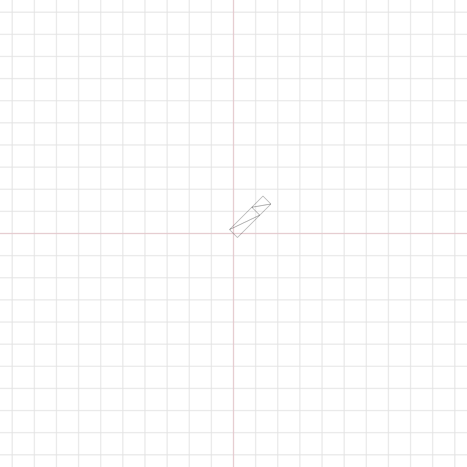
As you can see, this simple approach works reasonably well. However, problems arise at joints and corners. When we add bends to the line, the corner rendering is clearly incorrect:
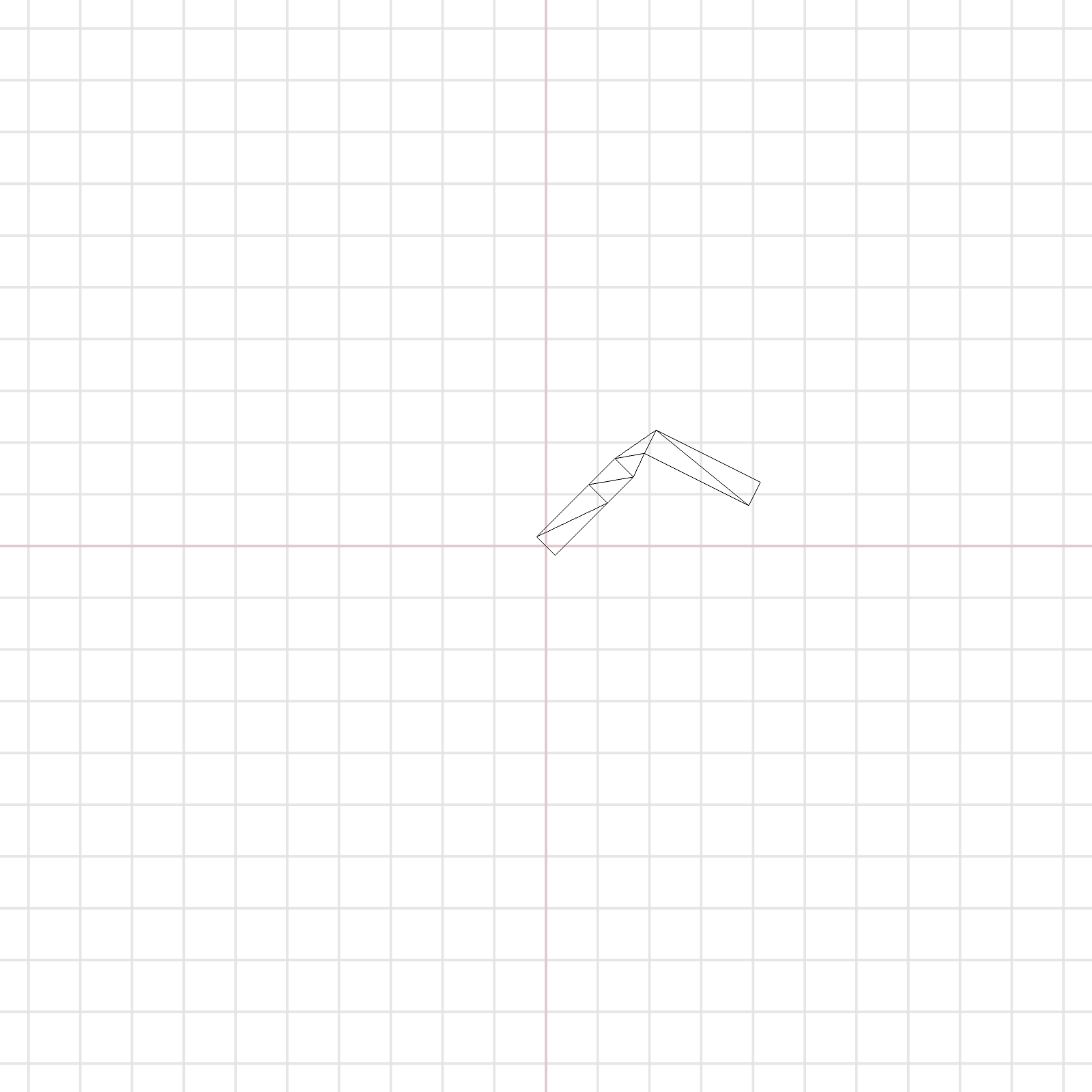
Adding color makes the issue even more apparent:
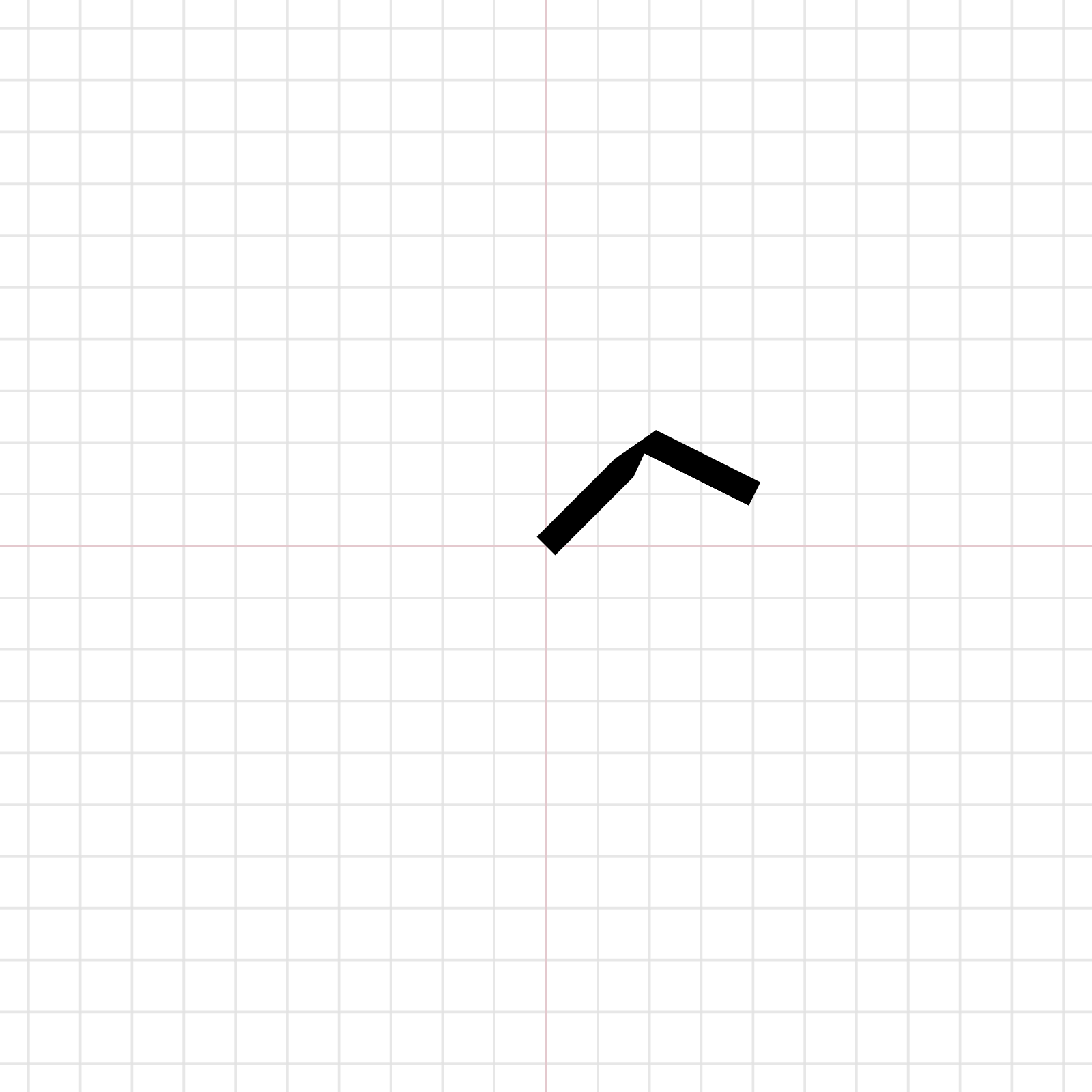
You can see the line pinched and collapsed completely at the joints.
Handling Joints and Corners
The root problem is that our current implementation only relies on the normal computed from the current point to the next point. While this ensures the two offset points are perpendicular to that single segment, it doesn’t give us the result we actually want.
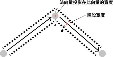
Here, we assume all vectors are normalized (unit vectors with a length of 1).
In this diagram, the points we actually want to sample are the upper and lower points along vector A, but the previous implementation used the two points from vector B instead. As a result, the subsequent vertex positions were calculated incorrectly.
At corners, we cannot simply take the normal of the next vector. Instead, we must rely on the normal derived from the sum of both the previous and next vectors.
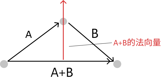
Originally, calculating the line width along the perpendicular component was just a simple multiplication. But because the corner angle is now governed by the normal of A + B, we must separately calculate the length of the perpendicular component projected onto this normal vector.
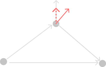
The projected length is calculated using the dot product of the two vectors. At this point, we can formalize our line-drawing strategy:
- Find the vector between the current point and the previous point (Vector A), and between the current point and the next point (Vector B).
- Calculate the normal of A and the normal of (A + B).
- Calculate the projection of the (A + B) normal onto Vector A’s normal.
- Divide the line width by the projected length.
- Offset one point upward and one point downward, each by half of the adjusted line width.
Writing the Vertex Shader
The projection calculation could be done in JavaScript, but since we have WebGL, we might as well write it directly in a shader:
uniform vec3 uColor;
uniform float uLineWidth;
attribute vec3 lineNormal;
varying vec3 vColor;

void main() {
  float width = (uLineWidth / lineNormal.z / 2.0);
  vec3 pos = vec3(position + vec3(lineNormal.xy, 0.0) * width);
  gl_Position = projectionMatrix * modelViewMatrix * vec4(pos, 1.0);
  vColor = uColor;
}
This example is implemented with Three.js. Some parameters are provided by Three.js’s built-in WebGL programs; you can check the official WebGLProgram documentation for more details.
Here, I passed several attributes and uniforms: position (original vertex coordinates), lineNormal (the computed normal vector and projection length), vColor (color), and uLineWidth (line width).
Implementation: BufferGeometry + ShaderMaterial
This implementation uses Three.js directly. However, the underlying principles are identical, so writing it in pure canvas + WebGL would work just as well.
BufferGeometry
export default class MyLineGeometry extends BufferGeometry {
  constructor(points) {
    super()
    const lineNormal = []
    const vertices = []
    const indices = []
    const last = points[points.length - 1]
    let currentIdx = 0

    points.forEach((p, index) => {
      if (index <= points.length - 2) {
        indices[index * 6 + 0] = currentIdx
        indices[index * 6 + 1] = currentIdx + 1
        indices[index * 6 + 2] = currentIdx + 2
        indices[index * 6 + 3] = currentIdx + 2
        indices[index * 6 + 4] = currentIdx + 1
        indices[index * 6 + 5] = currentIdx + 3
        currentIdx += 2
      } else if (points.length === 2 && index === 0) {
        indices[index * 6 + 0] = currentIdx
        indices[index * 6 + 1] = currentIdx + 1
        indices[index * 6 + 2] = currentIdx + 2
        indices[index * 6 + 3] = currentIdx + 2
        indices[index * 6 + 4] = currentIdx + 1
        indices[index * 6 + 5] = currentIdx + 3
        currentIdx += 2
      }

      vertices.push(p[0], p[1], 0)
      vertices.push(p[0], p[1], 0)
    })

    for (let i = 1; i < points.length; i++) {
      const point = points[i]
      const prev = points[i - 1]
      const next = points[i + 1] || null

      const a = new Vector2(point[0] - prev[0], point[1] - prev[1]).normalize()
      if (i === 1) { // first point
        lineNormal.push(-a.y, a.x, 1)
        lineNormal.push(-a.y, a.x, -1)
      }

      if (!next) {
        lineNormal.push(-a.y, a.x, 1)
        lineNormal.push(-a.y, a.x, -1)
      } else {
        const b = new Vector2(next[0] - point[0], next[1] - point[1]).normalize().add(a)
        const c = new Vector2(-b.y, b.x)
        const projection = c.clone().dot(new Vector2(-a.y, a.x).normalize())
        lineNormal.push(c.x, c.y, projection)
        lineNormal.push(c.x, c.y, -projection)
      }
    }

    this.setAttribute('position', new BufferAttribute(new Float32Array(vertices), 3));
    this.setAttribute('lineNormal', new BufferAttribute(new Float32Array(lineNormal), 3)); // [x, y, projection]
    this.setIndex(new BufferAttribute(new Uint16Array(indices), 1));
    const indexAttr = this.getIndex()
    this.position.needsUpdate = true;
    indexAttr.needsUpdate = true;
  }
}
Fragment Shader
varying vec3 vColor;
varying vec2 vUv;
void main() {
  float dist = length(vUv - 0.5);
  vec3 color = vColor;
  if (dist > 0.1) {
    color = smoothstep(dist - 0.02, dist, vUv.y) * color;
  }
  gl_FragColor = vec4(color, 1.0);
}
The ShaderMaterial implementation:
import { shaderMaterial } from "@react-three/drei";
import { Color, DoubleSide } from "three";

const MyLineShaderMaterial = shaderMaterial(
  {
    uColor: new Color(0.0, 0.0, 0.0, 1.0),
    uLineWidth: 10,
  },
  vertexShader,
  fragmentShader,
  (material) => material.side = DoubleSide
)

export default MyLineShaderMaterial;
Here I used @react-three/drei as a wrapper, but standard Three.js achieves the exact same result.
Results
Lines with Corners
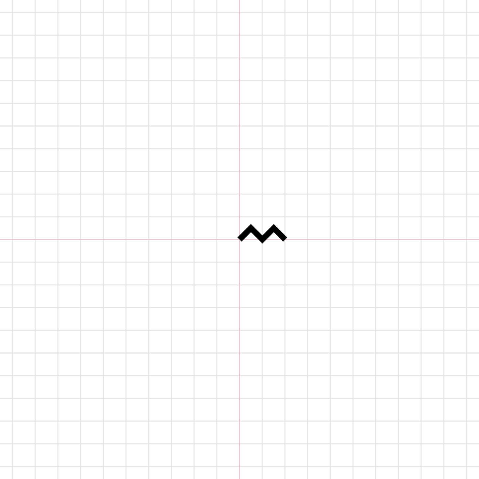
Sine Wave
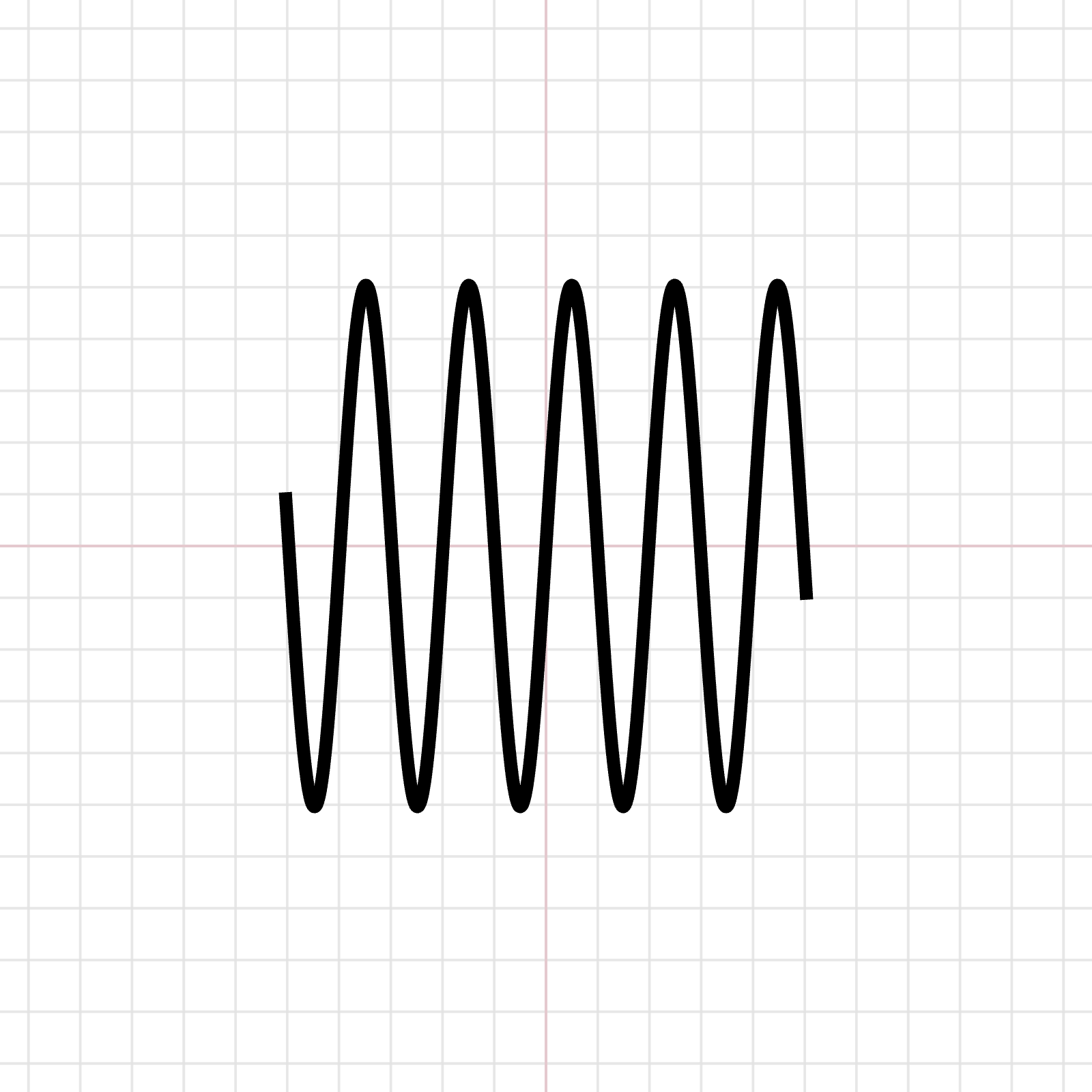
Success! A WebGL line with custom width is finally born.
To be honest, the current implementation isn’t ideal because changing point positions requires calling new BufferGeometry each time. In reality, we only need to update position and lineNormal. The next optimization step is allowing the geometry to update without having to recreate the instance.
The Next Challenge: Anti-aliasing
If you look closely at the lines, you’ll notice some aliasing (depending on the shape of the line). Without the browser smoothing things out automatically, anti-aliasing in WebGL must be handled manually.
Aliasing occurs because the edges of a line cannot completely fill a whole pixel, yet the screen’s minimum rendering unit is 1 pixel, leading to jagged edges.
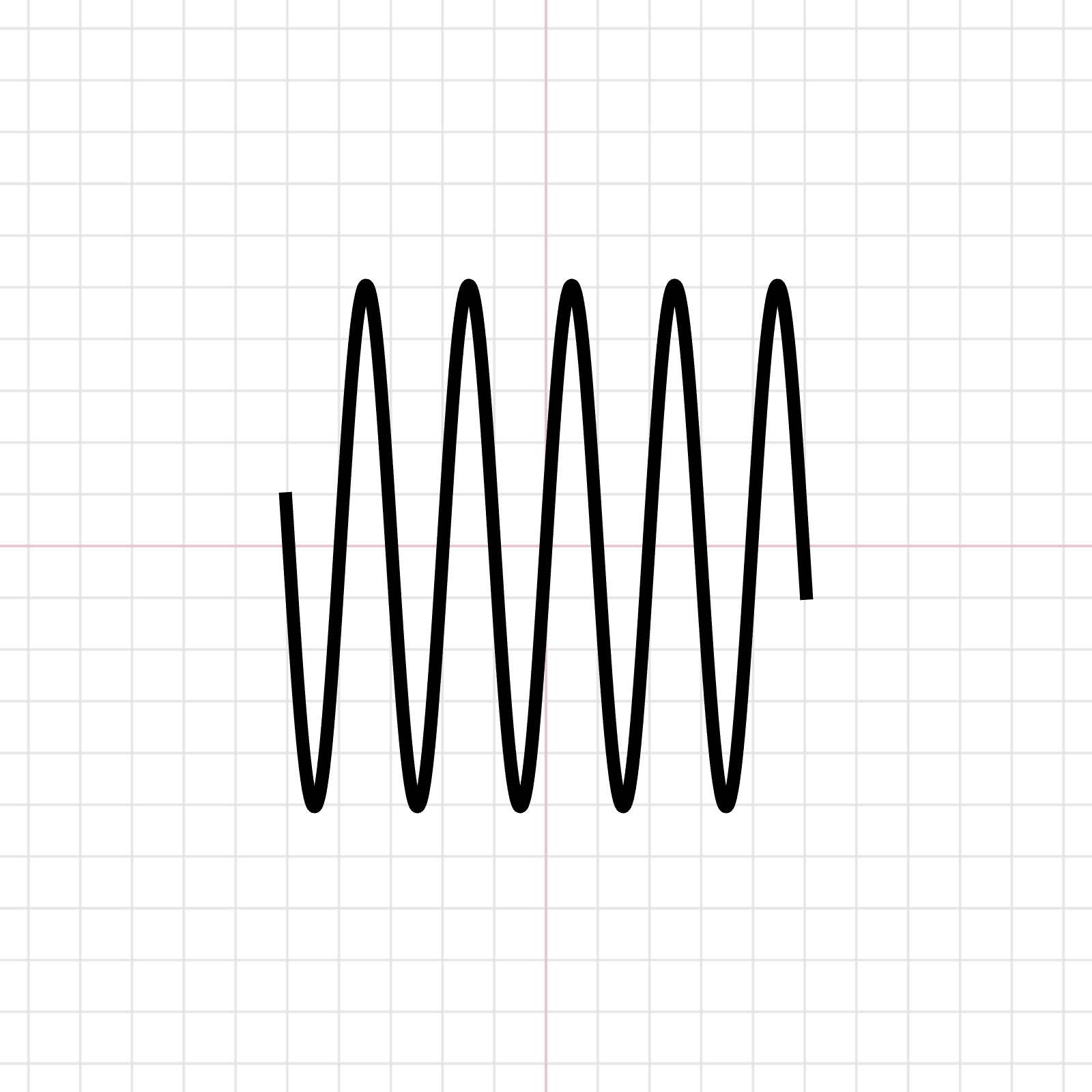
In our line-drawing scenario, there are several ways to tackle anti-aliasing:
- Use the fragment shader to render a smooth edge for the line
- Handle it directly via texture mapping
- Implement Prefiltered lines
My current implementation uses a fragment shader. Since Three.js handles UVs for us, it’s easy to calculate the boundaries based on vertex coordinates:
varying vec3 vColor;
varying vec2 vUv;
void main() {
  float dist = length(vUv - 0.5);
  vec3 color = vColor;
  float progress = smoothstep(1.0 - 0.03, 1.0, 1.0 - dist);
  if (dist > 0.9) {
    vec3 col = mix(color, vec3(1, 1, 1), progress);
    gl_FragColor = vec4(col, 1.0);
  } else {
    gl_FragColor = vec4(color, 1.0);
  }
}
However, the visual difference doesn’t look significant; I’m not sure if Three.js applies any other processing under the hood.
Conclusion
Drawing a line freely turned out to be far trickier than I anticipated. I originally assumed existing implementations could be plugged in directly, but they felt overly complex. Diving in to implement it myself revealed just how deep the rabbit hole really goes.
There are other implementation details worth exploring, but the current solution already satisfies my needs. Documenting them here for future reference:
- Rounded line caps/joins → requires designing additional vertex coordinates at corners
- Different colors per line segment
- Varying thickness along the line segment
Related Posts
- Recreating My Room with Three.js Using React Three Fiber, I brought my real room into the browser—turning physical objects into an interactive table of contents, and using spatial memory to tell the story of my life and work over the past few years.
- Things to Keep in Mind When Using Images in Frontend Development Expanding on Jake Archibald's article, this post organizes how modern responsive images should be written: why width/height are still necessary, when to use CSS aspect-ratio, how to choose between AVIF and WebP, and using picture/source/srcset for art direction on mobile devices.
- CSS field-sizing — Auto-resize Form Elements with a Single Line of CSS Previously, auto-resizing a textarea required listening to scrollHeight in JavaScript. With CSS field-sizing: content, a single line replaces it all, supporting textarea, input, and select. This article covers the pain points of older approaches and how to use field-sizing.
- Make Your Link Underlines Look Better: text-underline-offset By default, underlines sit very close to the text. Some designers dislike this look, and personally, I don't think it looks great either.