How to Build a Simple DIY Radio
Building a Simple DIY Radio
To me, the invention of the radio is truly magical: sound can travel across vast distances purely through radio waves, and then be reconstructed and played back through a receiver. In this post, I try building a simple DIY radio circuit to better understand the principles behind it. If we simplify the components of a radio, it mainly consists of three parts:
- Resonant circuit (Tuning circuit)
- Filtering / Rectification
- Amplifier circuit
Therefore, this article will introduce each of these three parts. Before that, let’s talk about how sound travels in the first place.
Transmitter: Amplitude Modulation (AM) and Frequency Modulation (FM)
An electric current flowing through a conductor generates an electromagnetic field around it. By adjusting the strength of the current, we can generate radio waves with different amplitudes and frequencies. Leveraging this characteristic, we can encode information onto radio waves and transmit them across great distances. The process of blending the original signal (data) into a radio wave is called modulation1, which is generally divided into Amplitude Modulation (AM) and Frequency Modulation (FM). Amplitude modulation does not change the frequency of the carrier wave, but alters its amplitude instead; frequency modulation, on the other hand, varies the frequency to carry the original signal.
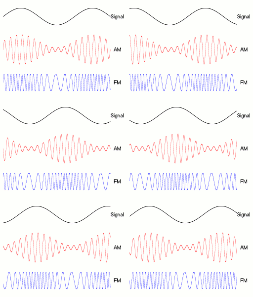
Image credit: Wikipedia (Berserkerus, CC BY-SA 2.5)
Through this method, we can “embed” sound into radio waves, which are then transmitted via broadcast towers. For example, the Fukuoka Tower is a radio tower located in Fukuoka.

Receiver: Resonant Circuit
So, how do we receive the signal on the receiving end? In basic electronics, we can use a resonant circuit to capture radio waves of a specific frequency. You can think of radio waves as weak alternating current (AC) signals surrounding us in the air.
When a capacitor and an inductor exist in an AC circuit, the voltage and current are constantly changing. When the current changes, the inductor creates an electromotive force (EMF) to oppose that change; the resulting EMF, in turn, introduces capacitive reactance in the capacitor, causing energy to continually oscillate back and forth between them. At a specific frequency, the inductive reactance and capacitive reactance cancel each other out, allowing the current at that specific frequency to reach its maximum. An antenna is fundamentally a conductor: when it intercepts radio signals, electromagnetic induction generates an electrical current inside it. The resonant circuit then isolates and receives the signal at that target frequency.
The resonant frequency can be calculated using the following formula:
where f is the frequency, L is the inductance value, and C is the capacitance value.
Filtering Circuit
In radio applications, the audio signal voltage needs to be positive, so a diode is added for rectification. A diode allows current to flow in only one direction.
Amplifier Circuit
The signal picked up from radio waves is extremely weak and almost impossible to hear directly; it must be amplified before it can produce audible sound. Signal amplification can be achieved using operational amplifiers (op-amps) or transistors. In practice, an op-amp IC specifically designed for audio is usually selected.
Implementation

The circuit is quite simple: at the front is a resonant circuit with a variable capacitor for easy frequency tuning. For the diode, I used a Schottky diode, which has a lower forward voltage drop than standard diodes, ensuring that even very weak signals can pass through. Instead of discrete transistors, the amplifier circuit uses Toshiba’s TA7368 audio power amplifier IC2. Finally, connect a speaker, and you’re good to go!
During testing, I found that the capacitance range of the variable capacitor was too narrow, which initially resulted in only a very muffled, faint sound. After some trial and error, I discovered that touching the metal part with my hand allowed the sound to come through clearly. This is because the human body also has some capacitance, which happened to shift the overall capacitance right into the broadcast frequency range!
Afterword
Honestly, hacking together a homemade radio circuit like this is quite rare nowadays. Usually, dedicated ICs handle everything, or frequency selection and volume adjustments are done via digital signals. Still, building one with your own hands and understanding the principles behind it is a lot of fun.
There’s also something known as a Foxhole Radio3. During World War II, without internet access and fearing detection by enemy forces, soldiers improvised radios that required absolutely no power. The design used copper wire as an antenna and inductor, and an oxidized razor blade paired with a pencil lead as a makeshift diode for rectification—running entirely on the energy harvested directly from the radio waves. For more details, check out this video:
Footnotes
Related Posts
- How to Prepare for Software Engineering Interviews Preparing for tech interviews has always been challenging. One of the most frustrating parts is the heavily one-sided power dynamic. As a candidate, it's hard to gauge their actual standards, and it's easy to spiral into self-doubt afterward. Let's talk about it.
- Words That Changed My Outlook on Life Feynman, Chaplin, and the movie Hyakumeter: from an insecure boy to someone capable of helping others, sharing the reflections and life philosophies that shaped me most.
- N Benefits of an Independent Website Why spend time running your own blog in an era dominated by short-form video and social media? Here are my thoughts after nearly a decade of blogging.
- Reflections on Fitness and Weight Training Sharing my thoughts and journey with weight training over the past period.