Semiconductors Driving Modern Society (Part 2)
Yesterday, we introduced the function of semiconductors and their actual operating principles (simplified version), and ended with this image:

This type of transistor is called a Bipolar Junction Transistor, commonly referred to as a BJT. However, in practical applications, another type of transistor is more widely used: the Field-Effect Transistor, abbreviated as MOSFET.
Field-Effect Transistors (MOSFET)
Like a bipolar junction transistor, a field-effect transistor has three main terminals: gate, drain, and source, along with a substrate (body).
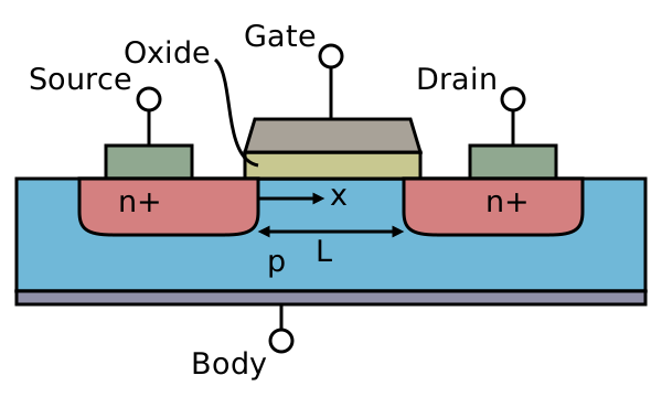
When a voltage is applied to the gate, an electron channel is created between the source and the drain, thereby conducting the circuit. Because we can control whether the circuit conducts by applying a voltage, it can function as a switch.
There are several reasons why MOSFETs are used more often than BJTs:
- There is a silicon oxide film between the gate and the P-type substrate, so no current flows even when a voltage is applied (high input impedance). As a result, its power consumption is relatively smaller than that of a BJT.
- The switching speed (frequency) of a MOSFET is much higher than that of a BJT.
- Due to its structural characteristics, a MOSFET is usually smaller than a BJT.
Thanks to these advantages, we predominantly use MOSFETs in semiconductor manufacturing processes.
Manufacturing Process
For a CPU or any other integrated circuit, the most fundamental component is the transistor; however, the placement and interconnection of these transistors are what really matter. To achieve this at an extremely small scale, the most critical manufacturing technique today is photolithography. The main principle involves turning the circuit layout into a photomask and exposing the circuit pattern onto the silicon wafer.
Since semiconductor manufacturing processes have advanced down to the scale of just a few nanometers, extremely precise operations are required. The frequently mentioned EUV (Extreme Ultraviolet) lithography uses light with an even shorter wavelength, making lithography machines essentially the key to semiconductor manufacturing. A single lithography machine alone can cost billions of NTD.
Packaging
Once the circuits are etched onto the wafer, they need to undergo packaging before they can actually be used by others. This is because the internal circuits are relatively fragile and require an outer shell for protection. Furthermore, the contact pads on the wafer are far too small, requiring a packaging facility to wire and bond these contacts for practical use. The same chip can come in different packaging styles, such as DIP, PGA, SMD, and more.
Hardware Description and Design
A single CPU easily contains billions of transistors. A scale like this cannot possibly be completed by a few people manually drawing schematics and routing wires; it generally requires computer assistance. Today, logic circuits are primarily designed using RTL (Register Transfer Level), with Verilog being one of the most prominent examples.
module half_adder(A, B, sum, c);
  input A, B;
  output sum, c;
  xor (sum, A, B);
  and (c, A, B);
endmodule
This looks very similar to code we write every day. However, because its underlying operation translates directly into physical circuitry, it is quite different from standard software programs. In physical circuits, operations execute simultaneously. In other words, this half adder does not calculate sum first and then c (carry); both are completed concurrently in a single cycle. Once the logic circuit is written, it is simulated and tested, and physical place-and-route begins only after ensuring it behaves as expected.
Applications
Transistors have far too many applications to list exhaustively, so I will share two common ones here.
CPU / MCU
CPUs and MCUs are both made up of countless transistors. But how can a bunch of transistors be combined to form a CPU or MCU?
In a very simplified view, the circuits inside a CPU can be broadly divided into several parts: control units, arithmetic logic units (ALU), and storage units (registers/caches). The control unit determines which branch of instructions to execute, the arithmetic unit handles data computation, and the storage unit holds data.
For details on how each unit can actually be simulated using circuits, you can refer to [Day 8] Top 3 Programming-Related Games (2) – TIS-100 & Turing Complete. Essentially, all functions can be constructed using logic gates, and logic gates can be implemented with transistors.
“Wait, but computers aren’t just 0s and 1s, right?” For instance, how can displays show such vibrant and varied colors? Indeed, these technologies involve much more than mere electrical signals. However, if we think of a display as a massive array of tiny LEDs whose brightness and color can be adjusted based on voltage levels, then the act of displaying an image can be abstracted into: “calculate the voltage needed for this color and where to show it.”
Displays also have control chips behind them; simply changing the value at a specific display memory address allows the chip to adjust the color for us. Thus, the entire process can be simplified even further into “calculating which memory address value needs to be changed.” As we can see, many problems, when broken down to their core, become computational problems—and as long as something can be computed, a CPU can be used.
Boost Converter
Suppose you have an IC that requires a 5V or 12V power supply, but a single dry-cell battery only provides 1.5V, and two only provide 3V. What should you do? As mentioned earlier, one of the primary functions of a transistor is acting as a “switch.” The principle of a boost converter relies on an inductor (coil). Inductors have a fascinating characteristic: when the current changes, the inductor generates an electromotive force (EMF) to oppose that change.

If we continuously toggle the switch on and off, allowing the inductor to repeatedly store energy and release it to charge a capacitor, we can obtain a voltage higher than the input voltage. This achieves the voltage boosting effect. When I first learned about this circuit, I found it mind-blowing—turns out boosting voltage is just turning a switch on and off repeatedly!
Of course, this isn’t magic. While theoretically you could boost the voltage infinitely, doing so would subject the MOSFET and the inductor to enormous power dissipation, virtually tantamount to a direct short circuit. Even if possible, two 1.5V dry-cell batteries hold limited energy; boosting the voltage too high would deplete them in no time.
Related Posts
- When a Measure Becomes a Target: From the Window Tax to Pull Request Counts I once wrote a script to tally how many PRs I contributed in a quarter, how many reviews I left, and how many tickets I closed, hoping to use numbers to prove my output to my manager. My manager simply remarked that performance isn't just about output. Years later, I finally understood—when a measure becomes a target, it ceases to be a good measure. From the British window tax and the Hanoi rat bounty to evaluating developers by PR counts today, the underlying mechanism is exactly the same.
- Using Cloudflare Images for Image Storage and Transformation Putting an image on a webpage is the simplest task in frontend development. But doing it properly—including resizing, generating multiple formats, and withstanding heavy traffic—is actually an entire end-to-end solution. Eventually, I offloaded everything to Cloudflare Images, keeping only a single original image.
- Stop Using AWS Access Keys Access Keys are an easily overlooked security risk in AWS. By pairing OIDC with IAM Roles, GitHub Actions can securely operate AWS resources without storing any secrets.
- Database Primary Keys: AUTO_INCREMENT, UUID, and UUIDv7 Backend developers often face the choice of primary keys: should you use auto-increment or UUID? What about collisions? How does UUIDv7 compare to created_at + index in performance? Here are the design decisions and benchmark results from testing 20 million rows.