How Chargers Work
Introduction
Electricity generation stems from a simple physical fact: electromagnetic induction. If the magnetic flux through an induction coil changes, electricity is produced.
While this is taken for granted today, it took Michael Faraday a considerable amount of experimentation to discover this wondrous principle of nature. Nikola Tesla later used the principle of electromagnetic induction to invent the alternator structure, laying a crucial foundation for modern power generation.
A change in the magnetic field is required to generate electricity, and kinetic energy (among other methods) is needed to induce that change. Power plants burn coal, natural gas, or use nuclear energy to boil water into steam; that steam drives magnets to rotate, and this rotation generates electricity. This is a vital cornerstone supporting human civilization.
To me, this is fascinating. What appears to be an immensely complex phenomenon called electricity boils down to one simple fact: electromagnetic induction.
AC vs. DC
Wall outlets in Taiwan supply power at 110V/60Hz. If you were to feed this electricity directly into electronic devices, they would be destroyed immediately. Not only would the 110V voltage fry most components, but the constantly alternating potential of AC power would also make discerning digital 0s and 1s virtually impossible. Therefore, we must convert alternating current (AC) into direct current (DC) at a stable voltage for electronics to function properly.
Since the voltage of AC power is constantly fluctuating, what exactly does “110V” refer to? This 110V refers to the RMS (Root Mean Square) value of the alternating current. When an AC voltage produces the same wattage across a resistor as a 110V DC voltage would, that is its RMS value. Using the RMS value as a common metric makes intuitive sense, since wattage is ultimately what we care about when operating electrical appliances.
Typical electronic devices usually run on operating voltages between 3.3V and 12V (depending on the product). How do we convert AC to DC?
The process of converting AC to DC generally involves several stages:
- Voltage transformation
- Rectification
- Voltage regulation / smoothing
- Step-down conversion
Voltage Transformation
Traditional transformers are relatively bulky, such as early laptop power bricks or power adapters for monitors. A transformer works on the principle of electromagnetic induction, stepping AC voltage up or down based on the ratio of turns between two distinct coils. The transformer is usually the largest component inside a charger, so shrinking its footprint is the key to making chargers lightweight and compact.
According to Faraday’s law of electromagnetic induction, the induced electromotive force can be determined by the following formula:
- Where is the average induced voltage across the coil
- is the frequency of the current
- is the number of turns in the coil
- is the cross-sectional area of the coil’s core
- is the magnetic flux density passing through the core
Looking at this formula, the number of turns, the cross-sectional area, and the magnetic flux density all influence the size of a transformer. If we want to reduce the physical area of the transformer, the most effective method is to increase the frequency (). However, standard mains AC input is generally fixed at a low frequency—60Hz in places like Taiwan. What can we do?
Rectification
Even after stepping down the voltage, the electricity remains AC; it still cannot be fed directly into electronic devices and requires further rectification.
The process of converting AC into DC is called rectification, which can be divided into full-wave rectification and half-wave rectification.
Because full-wave rectification offers higher conversion efficiency, it is commonly implemented using a bridge rectifier. A bridge rectifier leverages the unidirectional conductivity of diodes. When AC passes through a bridge rectifier, the negative half-cycles are inverted into positive ones, producing a waveform like this:
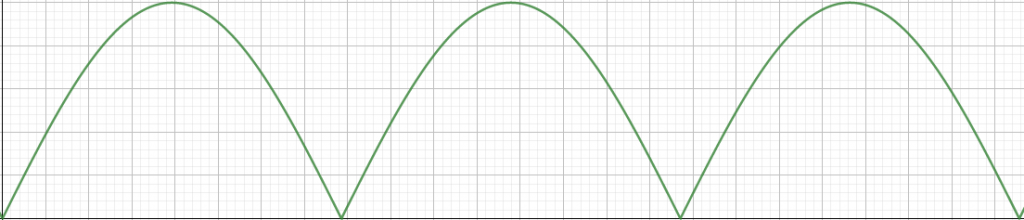
Although this is now technically DC, several issues remain:
- The voltage fluctuates wildly and is far from an ideal, steady DC voltage.
- The rectified voltage is still too high, hovering around 140V peak.
We can add capacitors to smooth out the output voltage and reduce ripple. Capacitors have the ability to charge and discharge; when the output voltage passes its peak and begins to drop, the capacitor discharges to slow the decline, smoothing out the output voltage curve.
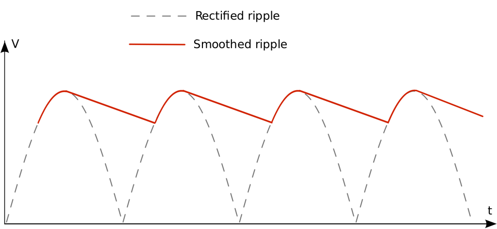
Even so, the voltage remains very high. How do we step it down?
Stepping Down the Voltage
Stepping down from ~140V to 5V requires the help of a transformer. Because transformers rely on electromagnetic induction, we actually need to convert our newly rectified DC back into AC!
So the whole process goes AC → DC → AC → DC? Yes, precisely. There is a crucial reason for doing this: to minimize the physical size of the transformer as much as possible.
Wikipedia documents the transformer transformation equations. While the math looks somewhat complex, one fact stands out: at a given magnetic flux density, the higher the input frequency, the smaller the required core area.
Therefore, as long as we find a way to make the frequency of the input voltage as high as possible, we can significantly reduce the charger’s size. But as mentioned, the input is currently DC—how do we turn it back into AC? The answer is high-speed switching. By constantly switching the current on and off, the current changes, which naturally induces electromagnetic effects.
Using the switching properties of MOSFETs or BJTs, switching frequencies can reach 100 kHz or even higher. By rapidly turning the switch on and off, we can reshape the DC waveform into an alternating one. A circuit designed this way is known as a Flyback Converter (Wikipedia).
Once converted to high-frequency AC via the Flyback Converter, a much smaller transformer can be used to step down the voltage. To convert the output back into DC, diodes and capacitors are once again added to rectify and smooth the current.
As mentioned earlier, while standard diodes allow current to flow in only one direction, their recovery time—the time it takes to switch from conducting to non-conducting—is relatively long. At frequencies reaching tens or hundreds of kilohertz, standard diodes fall short. To accommodate such high-speed switching, specialized components called Schottky diodes are commonly used for rectification.
Another approach is active rectification, also known as synchronous rectification, which uses the switching characteristics of transistors to rectify the current. The biggest advantage of using transistors for rectification is that conversion losses are lower than with diodes. However, this requires IC control and additional supporting components, making it more complex and costly than using Schottky diodes.
A widely discussed trend recently is GaN (Gallium Nitride) chargers. Due to the material properties of GaN, components can operate at much higher frequencies than conventional silicon transistors. This means the transformer can be shrunk even further, making it a technology well worth watching.
Charging and USB Power Delivery (PD)
Finally, our charger can output 5V! However, beyond going through all that trouble to convert AC into a stable 5V DC line, output-side control is also required. For instance, the charger must communicate with a phone’s charging port to negotiate fast charging, monitor temperatures, protect against short circuits, and more. For this reason, chargers house microcontrollers to handle this logic.
When people talk about fast charging, they usually refer to USB Power Delivery (PD) or Quick Charge (QC); here, we’ll focus on Power Delivery. Because USB Type-C features dedicated communication channels, configuration data can be transmitted over the CC (Configuration Channel) pin. This includes whether the device supports fast charging and the specific voltages it can accept. The charger can then adjust its output voltage accordingly.
Of course, implementing the complete Power Delivery protocol from scratch is no simple task, so dedicated integrated controller ICs are usually employed.
On the smartphone side, protection circuits and charging optimization systems are also built in. For example, when a lithium-ion battery is close to full capacity, the circuit throttles the charging current, stopping it completely once fully charged.
Conclusion
This post provides a broad overview of how electricity works in modern power adapters, focusing on how AC power is converted into DC for electronic devices:
- Rectify AC using a bridge rectifier
- Smooth and boost the effective DC voltage while reducing ripple using capacitors (or pi-filters)
- Step down voltage at high frequency using a transformer (Flyback Converter)
- Rectify AC back into DC once more using synchronous rectification or Schottky diodes
As a software engineer, I indirectly make my living off of electricity every single day, yet I realized I previously knew almost nothing about this gift from nature.
Converting raw AC into stable DC—and then optimizing the design from a product standpoint to make it smaller, more efficient, and safer—is built entirely upon fundamentals of physical science. That, right there, is the very essence of Engineering.
Related Posts
- When a Measure Becomes a Target: From the Window Tax to Pull Request Counts I once wrote a script to tally how many PRs I contributed in a quarter, how many reviews I left, and how many tickets I closed, hoping to use numbers to prove my output to my manager. My manager simply remarked that performance isn't just about output. Years later, I finally understood—when a measure becomes a target, it ceases to be a good measure. From the British window tax and the Hanoi rat bounty to evaluating developers by PR counts today, the underlying mechanism is exactly the same.
- Using Cloudflare Images for Image Storage and Transformation Putting an image on a webpage is the simplest task in frontend development. But doing it properly—including resizing, generating multiple formats, and withstanding heavy traffic—is actually an entire end-to-end solution. Eventually, I offloaded everything to Cloudflare Images, keeping only a single original image.
- Stop Using AWS Access Keys Access Keys are an easily overlooked security risk in AWS. By pairing OIDC with IAM Roles, GitHub Actions can securely operate AWS resources without storing any secrets.
- Database Primary Keys: AUTO_INCREMENT, UUID, and UUIDv7 Backend developers often face the choice of primary keys: should you use auto-increment or UUID? What about collisions? How does UUIDv7 compare to created_at + index in performance? Here are the design decisions and benchmark results from testing 20 million rows.