If you have any questions or feedback, pleasefill out this form
This post is translated by ChatGPT and originally written in Mandarin, so there may be some inaccuracies or mistakes.
DIY Simple Radio Receiver
The invention of the radio is quite magical to me. Through radio transmission, sound can travel vast distances and be reproduced by a radio receiver. In this article, I will attempt to build a simple radio circuit to understand the principles behind it. After simplifying the components of a radio, it can mainly be composed of three parts:
- Resonant Circuit
- Filtering
- Amplification Circuit
Thus, this article will introduce each of these three components. Before we dive in, let’s first discuss how sound propagates.
Transmitter: Amplitude Modulation (AM) and Frequency Modulation (FM)
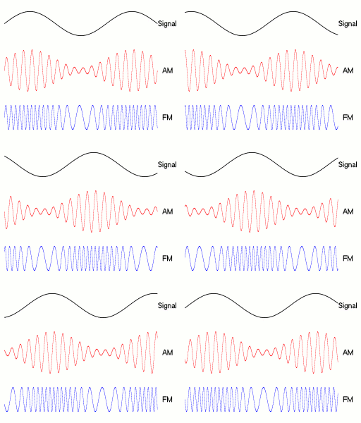
Electric current flowing through a conductor generates an electromagnetic field around it. By adjusting the strength of the current, we can produce radio waves with varying amplitudes and frequencies. This property allows us to place information on radio waves and transmit it over long distances. The process of mixing the original signal (data) with the radio wave is called modulation1, which can generally be divided into Amplitude Modulation (AM) and Frequency Modulation (FM). AM does not change the original frequency of the wave but alters its amplitude, while FM changes the frequency to carry the original signal.

Image credit: Wikimedia Commons (Berserkerus, CC BY-SA 2.5)
In this way, we can "embed" sound into radio waves and transmit it through a base station. For example, Fukuoka Tower is a transmission tower located in Fukuoka.

Receiver: Resonant Circuit
So how do we receive signals at the receiving end? In basic electronics, we can use a resonant circuit to capture radio waves at specific frequencies. You can think of radio waves as small alternating currents circulating around us.
In an alternating current circuit, the presence of capacitors and inductors means voltage and current are constantly changing. When the current changes, the inductor generates electromotive force to resist the change in current; this induced electromotive force then causes the capacitor to create reactance, leading to continuous absorption and release of energy between them. At a fixed frequency, the reactance of both can cancel each other out, resulting in maximum current at a specific frequency. The antenna is essentially a conductor; when it receives radio signals, it generates electromagnetic induction internally, producing current, which is then used by the resonant circuit to receive signals at specific frequencies.
The resonant frequency can be calculated using the following formula:
where f is the frequency, L is the inductance value, and C is the capacitance value.
Filtering Circuit
In radio applications, the voltage of sound is always positive. Therefore, we add a diode for rectification, which allows current to flow in one direction only.
Amplification Circuit
The signals received from the radio are quite weak and difficult to hear, requiring amplification to make the sound audible. Signal amplification can be achieved using operational amplifiers or transistors. In practice, we typically choose operational amplifier ICs designed specifically for audio applications.
Implementation

The circuit is simple: at the front is a resonant circuit that uses a variable capacitor for frequency adjustment. The diode used is a Schottky diode, which has a lower forward voltage drop than standard diodes, ensuring that even weak signals can pass through. The amplification circuit employs Toshiba's TA7368 audio amplifier2 instead of a transistor, and finally connecting a speaker completes the setup.
During the experiment, I found that the range of the variable capacitor was too limited, leading to very faint sound during initial tests. After some random adjustments, I discovered that placing my hand on the metallic part allowed me to receive sound properly, as my hand added just enough capacitance to fall within the radio frequency range.
Conclusion
In fact, a homemade radio circuit like this is quite rare in modern times. Usually, there are pre-designed ICs available for use, or frequency selection and volume adjustment are done via digital signals. However, it is quite fun to build one yourself and understand the underlying principles.
Additionally, there is something called Fox Radio3. During World War II, without the internet and with the risk of being detected by enemies, soldiers invented a radio that required no power. Its principle uses copper wire as an antenna and inductor, and oxidized razor blades and pencil leads as diodes for rectification, entirely powered by radio energy. For more details, you can check out this video:
Footnotes
If you found this article helpful, please consider buying me a coffee ☕ It'll make my ordinary day shine ✨
☕Buy me a coffee